
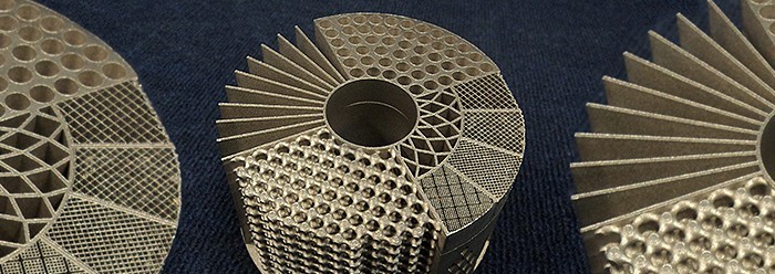
Heat sinks are a crucial part of lighting devices, dispersing the temperatures of the LED chip produced during operation. Light fixtures would simply overheat without having them. Improving heat sinks can have major benefits, for example for the airflow and thermal heat dispatching. To this end, teams of university researchers and engineers from various equipment providers have applied novel 3D printing technologies to demonstrate novel designs that can give heat sinks better efficiency for lighting applications. It comes as no surprise, that 3D printing technology significantly contributes to the development of making better, lighter and smarter heat sinks.
3D Printed Heat Sinks for Lighting
For many manufacturers of lighting equipment, natural convection of air-flows remains the preferred method for cooling the electronic components of a given light fixture. This method is cheap, simple to maintain and produces no noise or electromagnetic interference.
Natural convection, however, is limited in its scope, with medium to high power outputs tending to overwhelm the simple cooling system. Advanced 3D printing technology opens up doors to designs that could help significantly improve the efficiency of cooling bodies.

Heat-sinks help to guarantee a long service life of a light fixture and prevent it from early failure. Made from high thermal conductivity material such as aluminum or copper, these essential parts conduct heat from the electronic component towards the extremes of their own large surface areas. When the heat reaches these extremes, it can be convected to the air flowing overhead.
3D Printed Heat sinks: Lighter – Smaller – Better
Recently, researchers in the US, along with other European counterparts, have shown that 3D printed heatsinks could be lighter, smaller or better than conventional heatsinks. This conclusion comes from two linked projects at Oak Ridge National Laboratory and the University of Tennessee in Knoxville.
One proves that 3D printed aluminum heat sinks can at least equal and sometimes supersede the thermal conductivity of standard heatsink aluminum. The second has developed genetic algorithms that make use of the freedom of shape available from 3D printing to design heatsinks that fit in the same space as their conventional cousins but work better.

3D Printing Heatsinks – Pros & Cons
Now, with 3D printing capable of making heatsinks just as good as existing heatsinks the same shape, we may ask ourselves what benefits are available using the arbitrary shapes possible with 3D printing, and how these arbitrary shapes might be designed? Here are some insights into the benefits and challenges of the manufacturing process, as well as some practical designer tips.
Like any technology, 3D printing of metals has its advantages and disadvantages. The trick is to know both when it is appropriate to use it and find the ideal applications for the process. For example, metal printing is a good option for creating complex parts that need to be strong and lightweight. The parts are also fully dense and can include precision internal features that cannot be created using traditional machining. Printing is additive, so it generates minimal waste.
Another benefit of 3D metal printing has to do with its reliability. Although it may take a few attempts to find the best parameters, design, and orientation for building a part, once discovered, the process is tremendously consistent. It will result in the same part every time, build after build. Although this may be assumed as a given for any manufacturing process, the predictability and efficiency of metal printing should never be overlooked.
The tradeoff to 3D metal printing’s benefits is that speed and cost cannot be driving factors for those who want to pursue this technology. This is why aerospace and automotive industries have been the most committed early adopters of the technology, rather than the more conventional and highly-cost oriented lighting industry. The lightweight, strong designs translate well to their applications.

Build times for 3D metal printing are longer compared to those for plastic 3D printing. It typically requires several builds to fine-tune a part’s design for mass production through 3D metal printing.
Before committing to designing parts for metal printing, designers should consider the material that is preferred for the part. Although there are a lot of materials people claim can be used for 3D printing, there is a very limited number of metals that can be printed on the market. It takes years of research and effort to develop the process parameters for specified materials in certain machines. This is a tricky aspect of the technology.
3D Printing Materials and Finishes
Some of the most common and reliable metals for 3D printing include stainless steel, aluminum, titanium, cobalt chrome and Inconel alloy. Choosing the best material is vital for ensuring parts will perform as needed.
Another design aspect to consider before going with choosing 3D metal printing is the desired surface finish. The surface finish of 3D printed part is poor due to it being built layer by layer. It takes post-machining on printed parts to get aesthetically pleasing surface finishes. This can be done using CNC machining or manual surface grinding, sanding, or polishing.
It may seem obvious, but size is another limed parameter. Parts cannot be larger than the machine’s build platform, which varies from printer to printer. Although there is no standard Build-platform size, the most common dimensions are around 250 × 250 × 300 mm, or smaller.

a) Industrial design solutions; b) Topology-optimized LED heat sinks for vertical, and horizontal orientations with 1/2 and 1/8 symmetries; c) 3D printed topology-optimized design with additional support; post-processed design with removed support; and simplified interpretation manufactured by traditional techniques.
Source: Experimental validation of additively manufactured optimized shapes for passive cooling , Research Gate.
Designing parts for Metal Printing
Generally, there is a fair amount of trial and error that goes into perfecting a design. However, there are some common design pitfalls that can be avoided to streamline the process. It’s important for designers to have the process in mind when creating CAD models. Different 3D metal printers have different limitations due to the laser spot size and melt pool. Despite this, there are some general guidelines that should be followed when designing parts for metal printing:
Wall thicknesses
Walls that are too thin will begin to collapse under their own weight. Walls should be no thinner than 0.5 mm.
Hollows and Gaps
The limitations for gaps and holes may vary widely based on the printer being used, the metals being used, and part geometry. The general rule of thumb is to not design a gap or hole under 0.5 mm. Smaller gaps run the risk of the sides merging together and filling the empty space. On the other hand, supports need to be added for holes greater than 10mm.
Overhangs
0.5 mm is the maximum length that should be used for an overhang, and all downward facing structures need to be designed to a chamfer (more than a 45-deg. angle to the horizontal), with a concave or convex shape so the part can support itself. Support structures need to be included in the part’s design to exceed these guidelines.
Support Materials
Supports are needed for two reasons. The first is to hold parts to the substrate plate. The second is for heat dissipation. Any areas below 45 deg. from horizontal need support to be added. This applies to most of the metals.
Part orientation
Unlike other manufacturing processes, 3D printing creates parts with different mechanical properties in different build directions. In the X and Y directions, for example, parts have higher tensile strength than they do in the Z direction. Hence, part orientation needs to be considered prior to printing. This is especially true if parts are for mechanical/structural purposes where a certain area will sustain some degree of pressure and stress.
There is also an aesthetic element to part orientation. Downfacing surface areas of printed parts will have a poorer surface finish compared to the top-facing surfaces. If certain areas of a part need better surface finishes, it should be taken into consideration during part orientation. For complex parts, it is important that part orientation is such that if there are supports that may affect part function, they can be removed.
Trends in Metal Printing
In the near future, hybrid additive/subtractive machines will find their niche. It is not uncommon to find metal printing and CNC machining as part of a single production line. CNC machining may be needed to remove supports added to make a printed metal part. With a plastic printed object, supports can sometimes be manually removed simply by snapping them off. This is not the case with metal printing where removing supports takes a significant amount of time and effort. Once supports are removed, surface work (a time-consuming process) may be required as well. Combining these processes in one machine could be very beneficial.
3D Printed Heat Sinks – Future Outlook
Although 3D metal printing is not as easy as 3D plastic printing, the process of perfecting a design is worth it due to the higher engineering standard of the process. Although combined additive and subtractive machines will grow the market, traditional 3D metal printers will as well. There may seem to be a lot of limitations when it comes to metal printing, the industry fully expects the technology to go mainstream. It can be used to build parts that would be impossible by any other process due to complexity.
The key to metal printing’s growth and adoption will depend on widespread knowledge of designing parts for 3D printing. Some responsibility will fall on manufacturers to find avenues to share their knowledge with designers and one another.
The generally longer build times will begin to dissolve as new generations of metal printers come to market and the technology is perfected. Time will also lead to a wider range of metal powders to use for the process. Overall, 3D metal printing will likely prove to be the greatest development in low-volume manufacturing of metal parts over the next 50 years.
Conclusions
From what we at 3DPrinting.Lighting have read, heard and seen, we may conclude that the many optimization efforts to date result in significant material savings and design improvements of passive LED coolers. The possibility to account for several physical fields and their complex interaction, provides close to optimal utilization of the heat sink material and moves performance bounds close to the limit.
For such broadly applied and well-studied devices, reduction upto 20% in material utilization in unison with a 21-23% temperature decrease is still achievable, fully demonstrating the potential of 3D printed heat sinks. Optimized designs can be produced using 3D printing techniques or can be simplified further making them suitable for traditional manufacturing with only a small loss of performance. Higher computational efforts are required to account for additional physical effects and practical constraints.
The benefits in material savings and decreased temperature justify a certain cost increase in the design phase. Extensions to more complex multi-physical interactions including heat transfer in turbulent flows, magnetic refrigeration or cooling are still in their infancy, but cater for further future improvements in energy consumption of thermal and other systems!
This post was kindly inspired by Electronics Weekly, MachineDesign.com and the research study Optimized Shapes for passive cooling by researchers of the Universities of Denmark and Manchester.


